VLANS

Network performance is an important factor in an organization's productivity. One of the technologies used to improve network performance is the separation of large broadcast domains into smaller ones. By design, routers block broadcast traffic on an interface. However, routers normally have a limited number of LAN interfaces. The primary role of a router is to move information between networks, not to provide network access to end devices.
The role of providing access to a LAN is normally reserved for an access layer switch. A virtual local area network (VLAN) can be created on a Layer 2 switch to reduce the size of broadcast domains, similar to a Layer 3 device. VLANs are often incorporated into network design, making it easier for a network to support an organization's goals. Although VLANs are primarily used within switched local area networks, modern implementations of VLANs can span MANs and WANs.
This chapter describes how to configure, manage, and troubleshoot VLANs and VLAN trunks. It will also explore security considerations and strategies related to VLANs and trunks, and best practices for VLAN design.
VLAN segmentation
VLAN definitions
Within a switched internetwork, VLANs provide segmentation and organizational flexibility. VLANs provide a way to group devices within a LAN. A group of devices within a VLAN communicate as if they were on the same wire. VLANs are based on logical connections rather than physical connections.
VLANs allow an administrator to segment networks based on factors such as role, project team, or application, without regard to the physical location of the user or device. Devices within a VLAN behave as if they were in their own independent network, even if they share a common infrastructure with other VLANs. Each switch port can belong to a VLAN, and unicast , broadcast , and multicast packets are only forwarded and flooded to terminals within the VLAN where the packets originated. Each VLAN is considered a separate logical network and packets destined for stations not belonging to the VLAN must be routed through a device that supports routing.
 Determine VLAN groups
A VLAN creates a logical broadcast domain that can span multiple physical LAN segments. VLANs improve network performance by splitting large broadcast domains into smaller ones. If a device in one VLAN sends a broadcast Ethernet frame, all devices in the VLAN receive the frame, but devices in other VLANs do not.
VLANs enable the implementation of access and security policies based on specific groups of users. Each switch port can be assigned to only one VLAN (excluding a port connected to an IP phone or to another switch).
Benefits of VLANs
User productivity and network adaptability are important to a company's growth and success. VLANs make it easier to design a network to support an organization's goals. The main benefits of using VLANs are as follows:
- Security – Groups with sensitive data are separated from the rest of the network, reducing the chance of breaches of confidential information. As shown in the image, the faculty computers are on VLAN 10 and are completely separated from student and guest data traffic.
- Cost Savings – Cost savings result from reduced need for expensive network upgrades and more efficient use of existing bandwidth and uplinks.
- Better performance – Splitting flat Layer 2 networks into multiple logical workgroups (broadcast domains) reduces unnecessary traffic on the network and improves performance.
- Shrink Broadcast Domains – Splitting a network into VLANs reduces the number of devices in the broadcast domain . As shown in the figure, there are six computers on this network, but there are three broadcast domains: faculty, student, and guest.
- Improved IT staff efficiency – VLANs make it easier to manage the network because users with similar network requirements share the same VLAN. When a new switch is shipped, all policies and procedures already configured for the specific VLAN are implemented when the ports are assigned. It is also easy for IT staff to identify the function of a VLAN by giving it an appropriate name. In the figure, VLAN 10 is named "Faculty", VLAN 20 is named "Student", and VLAN 30 is "Guest" for easy identification.
- Easier project and application management – VLANs bring users and network devices together to support business or geographic requirements. Having separate functions makes managing a project or working with a specialized application easier; an example of such an application is an e-learning development platform for the faculty.
 Benefits of VLANs
Each VLAN in a switched network corresponds to an IP network; therefore, the VLAN design must take into account the implementation of a hierarchical network addressing scheme. Hierarchical network addressing means that IP network numbers are applied to network segments or VLANs in an ordered manner that takes into account the network as a whole. Blocks of contiguous network addresses are reserved for and configured on devices in a specific area of the network, as shown in the figure.
Types of VLANs
There are a number of different types of VLANs used in modern networks. Some VLAN types are defined by traffic classes. Other types of VLANs are defined by the specific function they serve.
Data VLAN
A data VLAN is a VLAN configured to carry user-generated traffic. A VLAN with voice or management traffic would not be a data VLAN. It is common practice to separate voice and management traffic from data traffic. A data VLAN is also called a user VLAN. Data VLANs are used to divide the network into groups of users or devices.
Standard VLAN
All switch ports become part of the default VLAN after the first boot of a switch loading the default configuration. Switch ports that participate in the standard VLAN are part of the same broadcast domain. This allows any device connected to a switch port to communicate with other devices on other switch ports. The default VLAN for Cisco switches is VLAN 1. In the figure, the show vlan brief command has been issued on a switch with the default configuration. Note that all ports are assigned to VLAN 1 by default.
VLAN 1 has all the functions of any VLAN, except that it cannot be renamed or deleted. By default, all Layer 2 control traffic is associated with VLAN 1.
Native VLAN
A native VLAN is assigned to an 802.1Q trunk port. Trunk ports are the links between switches that support the transfer of traffic associated with more than one VLAN. An 802.1Q trunk port supports traffic coming from many VLANs (tagged traffic), as well as traffic not coming from a VLAN (untagged traffic). Tagged traffic refers to traffic that has a 4-byte tag inserted into the original Ethernet frame header, specifying the VLAN to which the frame belongs. The 802.1Q trunk port places untagged traffic on the native VLAN, which is VLAN 1 by default.
Native VLANs are defined in the IEEE 802.1Q specification to maintain backward compatibility with untagged traffic common in older LAN scenarios. A native VLAN serves as a common identifier at opposite ends of a trunk link.
It is a best practice to configure the native VLAN as an unused VLAN, separate from VLAN 1 and other VLANs. In fact, it is not uncommon to dedicate a fixed VLAN to the role of the native VLAN for all trunk ports in the switched domain.
Management VLAN
A management VLAN is any VLAN configured to access a switch's management capabilities. VLAN 1 is the management VLAN by default. To create the management VLAN, that VLAN's virtual switch interface (SVI) is assigned an IP address and subnet mask, allowing the switch to be managed via HTTP, Telnet, SSH, or SNMP. Because the out-of-the-box configuration of a Cisco switch has VLAN 1 as the default VLAN, VLAN 1 would be a poor choice for the management VLAN.
Historically, the management VLAN for a 2960 switch was the only active SVI. On 15.x releases of the Cisco IOS for Catalyst 2960 Series switches, it is possible to have more than one active SVI. With Cisco IOS 15.x, the specific active SVI assigned for remote management must be documented. Although a switch can theoretically have more than one management VLAN, having more than one increases its exposure to network attacks.
Switch# show vlan brief

VLAN Name                Status    Ports
---- ------------------- --------- -----------------------
1    default             active    Fa0/1,  Fa0/2,  Fa0/3,  Fa0/4
                                   Fa0/5,  Fa0/6,  Fa0/7,  Fa0/8
                                   Fa0/9,  Fa0/10, Fa0/11, Fa0/12
                                   Fa0/13, Fa0/14, Fa0/15, Fa0/16
                                   Fa0/17, Fa0/18, Fa0/19, Fa0/20
                                   Fa0/21, Fa0/22, Fa0/23, Fa0/24
                                   Gi0/1,  Fi0/2
1002 fddi-default        act/unsup
1003 token-ring-default  act/unsup
1004 fddinet-default     act/unsup
1005 trnet-default       act/unsup
In the example above, all ports are currently assigned to the default VLAN 1. No native VLAN is explicitly assigned and no other VLANs are active; therefore, the network is designed with the native VLAN, the same as the management VLAN. This is considered a safety risk.
Voice VLANs
A separate VLAN is required to support Voice over IP (VoIP). VoIP traffic required:
- Guaranteed bandwidth to ensure voice quality
- Transmission priority over other types of network traffic
- Ability to be routed around busy areas on the network
- Delay of less than 150 ms over the network
To meet these requirements, the entire network must be designed to support VoIP. The details of configuring a network to support VoIP are beyond the scope of this course, but it is useful to summarize how a voice VLAN works between a switch, a Cisco IP phone, and a computer.
 Voice VLAN
VLANs in a multi-switched network
Vlan Trunks
A trunk is a point-to-point connection between two network devices that carry more than one VLAN. A VLAN trunk extends VLANs across an entire network. Cisco supports IEEE 802.1Q for coordinating trunks on Fast Ethernet, Gigabit Ethernet, and 10-Gigabit Ethernet interfaces.
VLANs wouldn't be very useful without VLAN trunks. VLAN trunks allow all VLAN traffic to be distributed between switches, so that devices that are in the same VLAN but connected to different switches can communicate without going through a router. A VLAN trunk does not belong to a specific VLAN; rather, it is a channel for multiple VLANs between switches and routers. A trunk can also be used between a network device and a server or other device equipped with an appropriate 802.1Q-compatible NIC. By default, on a Cisco Catalyst switch, all VLANs are supported on a trunk port.
In the figure, the connections between switches S1 and S2, and S1 and S3 are configured to send traffic from VLANs 10, 20, 30, and 99 across the network. This network could not function without VLAN trunks.
Manage broadcast domains with VLANs
Network without VLANs
In normal operation, when a switch receives a broadcast frame on one of its ports, it forwards the frame through all other ports except the port where the broadcast was received. In the animation in Figure 1, the entire network is configured in the same subnet (172.17.40.0/24) and no VLANs are configured. As a result, when the faculty computer (PC1) sends a broadcast frame, switch S2 sends that broadcast frame out of all its ports. Ultimately, the entire network receives the broadcast because the network is one broadcast domain.
 Without VLAN segmentation
Network with VLANs
As shown in the animation below, the network is segmented using two VLANs. Faculty devices are assigned to VLAN 10 and student devices are assigned to VLAN 20. When a broadcast frame is sent from the faculty computer, PC1, to switch S2, the switch forwards that broadcast frame only to those switch ports configured to support VLAN 10.
 With LAN segmentation
The ports connecting switches S2 and S1 (ports F0/1) and between S1 and S3 (ports F0/3) are trunks and are configured to support all VLANs in the network.
When S1 receives the broadcast frame on port F0/1, S1 forwards that broadcast frame from the only other port configured to support VLAN 10, which is port F0/3. When S3 receives the broadcast frame on port F0/3, it forwards that broadcast frame from the only other port configured to support VLAN 10, which is port F0/11. The broadcast frame arrives at the only other computer on the network configured in VLAN 10, which is the faculty computer PC4.
When VLANs are deployed on a switch, the transmission of unicast, multicast, and broadcast traffic from a host in a given VLAN is limited to the devices located in that VLAN.
Label Ethernet frames for VLAN identification
Catalyst 2960 series switches are Layer 2 devices. They use the Ethernet frame header information to forward packets. They don't have routing tables. The standard Ethernet frame header does not contain information about the VLAN to which the frame belongs; so when Ethernet frames are placed on a trunk, information about the VLANs they belong to must be added. This process, called tagging, is accomplished using the IEEE 802.1Q header, specified in the IEEE 802.1Q standard. The 802.1Q header contains a 4-byte tag inserted into the original Ethernet frame header, which specifies the VLAN to which the frame belongs.
 Fields in an Ethernet 802.1Q frame
When the switch receives a frame on a port configured in access mode and assigned a VLAN, the switch inserts a VLAN tag into the frame header, recalculates the FCS, and sends the tagged frame out a trunk port.
VLAN tag field details - The VLAN tag field consists of a Type field, a Priority field, a Canonical Format Identifier field, and a VLAN ID field:
- Type – A 2-byte value called the tag protocol ID (TPID) value. For Ethernet it is set to hexadecimal 0x8100.
- User Priority – A 3-bit value that supports level or service implementation.
- Canonical Format Identifier (CFI) – A 1-bit identifier that allows Token Ring frames to be transferred over Ethernet connections.
- VLAN ID (VID) – A 12-bit VLAN identification number that supports up to 4096 VLAN IDs.
After the switch inserts the Type and Tag control information fields, it recalculates the FCS values and inserts the new FCS into the frame.
Native VLANs and 802.1Q tagging
Tagged frames on the native VLAN
Some devices that support trunking add a VLAN tag to native VLAN traffic. Control traffic sent on the native VLAN should not be tagged. If an 802.1Q trunk port receives a tagged frame with the same VLAN ID as the native VLAN, the frame is dropped. Therefore, when configuring a switch port on a Cisco switch, you must configure devices so that they do not send tagged frames on the native VLAN. Third-party devices that support tagged frames on the native VLAN include IP phones, servers, routers, and non-Cisco switches.
Untagged frames on the native VLAN
When a Cisco switch trunk port receives untagged frames (which is unusual in a well-designed network), it forwards those frames to the native VLAN. If there are no devices associated with the native VLAN (which is not unusual) and there are no other trunk ports (which is not unusual), the frame is dropped. The default native VLAN is VLAN 1. When configuring an 802.1Q trunk port, a default Port VLAN ID (PVID) is assigned the value of the native VLAN ID. All untagged traffic entering or leaving the 802.1Q port is forwarded based on the PVID value. For example, if VLAN 99 is configured as the native VLAN, the PVID is 99 and all untagged traffic is forwarded to VLAN 99. If the native VLAN is not reconfigured, the PVID value is set to VLAN 1.
 native vlans and 802.1q tagging
In the figure, PC1 is connected to an 802.1Q trunk connection via a hub. PC1 sends untagged traffic that the switches associate with the native VLAN configured on the trunk ports and forward accordingly. Tagged traffic on the trunk received by PC1 is dropped. This scenario reflects poor network design for several reasons: it uses a hub, there is a host connected to a trunk link, and it implies that the switches have access ports assigned to the native VLAN. But it illustrates the motivation for the IEEE 802.1Q specification for native VLANs as a means to handle legacy scenarios.
Voice VLAN tagging
Remember that to support VoIP, a separate voice VLAN is required.
An access port used to connect a Cisco IP phone can be configured to use two separate VLANs: a VLAN for voice traffic and another VLAN for data traffic from a device connected to the phone. The link between the switch and the IP phone acts as a trunk for both voice VLAN traffic and data VLAN traffic.
 Voice VLAN tagging
The Cisco IP Phone includes an integrated 10/100 switch with three ports. The ports provide dedicated connections to these devices:
- Port 1 connects to the switch or other VoIP device.
- Port 2 is an internal 10/100 interface that carries the IP telephone traffic.
- Port 3 (access port) connects to a PC or other device.
On the switch, access is configured to send Cisco Discovery Protocol (CDP) packets that instruct a connected IP phone to send voice traffic to the switch in one of three ways, depending on the type of traffic:
- In a voice VLAN tagged with a Layer 2 Class of Service (CoS) priority value.
- In an access VLAN tagged with a Layer 2 CoS priority value.
- In an access VLAN, untagged (no Layer 2 CoS priority value).
In the image above, the student computer PC5 is connected to a Cisco IP phone and the phone is connected to switch S3. VLAN 150 is designed to carry voice traffic, while PC5 is in VLAN 20, which is used for student data.
VLAN assignment
VLAN ranges on Catalyst switches
Different Cisco Catalyst switches support different numbers of VLANs. The number of supported VLANs is large enough to meet the needs of most organizations. For example, the Catalyst 2960 and 3560 series switches support more than 4,000 VLANs. Normal range VLANs on these switches are numbered from 1 to 1,005 and extended range VLANs are numbered from 1,006 to 4,094. The figure illustrates the available VLANs on a Catalyst 2960 switch running Cisco IOS Release 15.x.
- Normal range VLANs
- Used in small and medium businesses and corporate networks.
- Identified by a VLAN ID between 1 and 1005.
- IDs 1002 through 1005 are reserved for Token Ring and FDDI VLANs.
- IDs 1 and 1002 to 1005 are created automatically and cannot be deleted.
- Configurations are stored in a VLAN database file called vlan.dat. The vlan.dat file is located in the switch's flash memory.
- The VLAN Trunking Protocol (VTP), which helps manage VLAN configurations between switches, can only learn and store normal-range VLANs.
- Extended range VLANs
- Enables service providers to extend their infrastructure to a larger number of customers. Some international enterprises may be large enough to require longer range VLAN IDs.
- Are identified by a VLAN ID between 1006 and 4094.
- Configurations are not written to the vlan.dat file.
- Supports fewer VLAN features than normal range VLANs.
- Are saved to the active configuration file by default.
- VTP does not learn extended range VLANs.
Switch# show vlan brief

VLAN Name                Status    Ports
---- ------------------- --------- -----------------------
1    default             active    Fa0/1,  Fa0/2,  Fa0/3,  Fa0/4
                                   Fa0/5,  Fa0/6,  Fa0/7,  Fa0/8
                                   Fa0/9,  Fa0/10, Fa0/11, Fa0/12
                                   Fa0/13, Fa0/14, Fa0/15, Fa0/16
                                   Fa0/17, Fa0/18, Fa0/19, Fa0/20
                                   Fa0/21, Fa0/22, Fa0/23, Fa0/24
                                   Gi0/1,  Fi0/2
1002 fddi-default        act/unsup
1003 token-ring-default  act/unsup
1004 fddinet-default     act/unsup
1005 trnet-default       act/unsup
Create a VLAN
When configuring normal range VLANs, the configuration details are stored in flash memory on the switch in a file called vlan.dat. Flash memory is persistent and does not require copy running-config startup-config. However, because other details are often configured on a Cisco switch at the time VLANs are created, it is a good practice to save ongoing configuration changes to the startup configuration.
 VLAN commands
The table above shows the Cisco IOS command syntax used to add and name a VLAN to a switch. Naming each VLAN is considered a best practice in switch configuration.
 Configure VLAN
Previous figure shows how the student VLAN (VLAN 20) is configured on switch S1. In the topology example, the student computer (PC2) is not yet associated with a VLAN, but it does have the IP address 172.17.20.22.
In addition to entering a single VLAN ID, a range of VLAN IDs separated by commas or a range of VLAN IDs separated by hyphens can be entered using the vlan vlan-id command. For example, use the following command to create VLANs 100, 102, 105, 106, and 107:
S1 (config) # vlan 100,102,105-107
Assign ports to VLANs
After you create a VLAN, the next step is to assign ports to the VLAN. An access port can belong to only one VLAN at a time; An exception to this rule is that of a port connected to an IP phone. In that case, there are two VLANs associated with the port: one for voice and one for data.
 Assign ports to VLANs
The table above shows the syntax for defining a port as an access port and assigning it to a VLAN. The switchport mode access command is optional, but highly recommended as a security best practice. This command changes the interface to permanent access mode.
In the example in the figure below, VLAN 20 is assigned to port F0/18 on switch S1; therefore, the student computer (PC2) is in VLAN 20. If VLAN 20 is configured on other switches, the network administrator knows that the other student computers are in the same subnet as PC2 (172.17.20.0/24).

The switchport access vlan command forces the creation of a VLAN if one does not already exist on the switch. For example, VLAN 30 is not present in the switch's show vlan brief output. If the switchport access vlan 30 command is entered on an interface with no previous configuration, the switch displays:
% Access VLAN does not exist. Creating vlan 30
Change VLAN port membership
There are a number of ways to change VLAN port membership. The table below shows the syntax for changing a switch port to VLAN 1 membership using the command without switch port access vlan interface configuration mode.
 Change VLAN port
Interface F0/18 was previously assigned to VLAN 20. The vlan command no switchport access was entered for interface F0/18. Examine the output in the show vlan brief command that immediately follows, as shown in the example below. The show vlan brief command displays the VLAN assignment and membership type for all switch ports. The show vlan brief command displays one line for each VLAN. The output for each VLAN includes the VLAN name, status, and switch ports.
S1(config)# int Fa0/18
S1(config-if)# no switchport access vlan
S1(config-if)# end

S1# show vlan brief

VLAN Name                Status    Ports
---- ------------------- --------- -----------------------
1    default             active    Fa0/1,  Fa0/2,  Fa0/3,  Fa0/4
                                   Fa0/5,  Fa0/6,  Fa0/7,  Fa0/8
                                   Fa0/9,  Fa0/10, Fa0/11, Fa0/12
                                   Fa0/13, Fa0/14, Fa0/15, Fa0/16
                                   Fa0/17, Fa0/18, Fa0/19, Fa0/20
                                   Fa0/21, Fa0/22, Fa0/23, Fa0/24
                                   Gi0/1,  Fi0/2
20   student             active
1002 fddi-default        act/unsup
1003 token-ring-default  act/unsup
1004 fddinet-default     act/unsup
1005 trnet-default       act/unsup
VLAN 20 is still active even though no ports are assigned to it. Examine the output of the example below show interfaces fa0/18 switchport that the access VLAN for interface F0/18 has been reset to VLAN 1.
S1# show interfaces fa0/18 switchport
Name: Fa0/18
Switchport : Enabled
Administrative Mode: static access
Operational Mode: down
Administrative Trunking Encapsulation: dot1q
Negotiation of Trunking: Off
Access Mode VLAN: 1 (default)
Trunking Native Mode VLAN: 1 (default)
A port can easily have its VLAN membership changed. It is not necessary to first remove a port from a VLAN to change the VLAN membership. When an gateway's VLAN membership is reassigned to another existing VLAN, the new VLAN membership simply replaces the previous VLAN membership. In the example below, port F0/11 is assigned to VLAN 20.
S1# configure terminal
S1(config)# interface Fa0/11
S1(config-if)# switchport mode access
S1(config-if)# switchport access vlan 20
S1(config-if)# end

S1# show vlan brief

VLAN Name                Status    Ports
---- ------------------- --------- -----------------------
1    default             active    Fa0/1,  Fa0/2,  Fa0/3,  Fa0/4
                                   Fa0/5,  Fa0/6,  Fa0/7,  Fa0/8
                                   Fa0/9,  Fa0/10, Fa0/12, Fa0/13
                                   Fa0/14, Fa0/15, Fa0/16, Fa0/17
                                   Fa0/18, Fa0/19, Fa0/20, Fa0/21
                                   Fa0/22, Fa0/23, Fa0/24, Gi0/1
                                   Fi0/2
20   student             active    Fa0/11
1002 fddi-default        act/unsup
1003 token-ring-default  act/unsup
1004 fddinet-default     act/unsup
1005 trnet-default       act/unsup
Delete VLANs
In the figure, the no vlan vlan-id global configuration mode command is used to remove VLAN 20 from the switch. Switch S1 had a minimal configuration with all ports in VLAN 1 and an unused VLAN 20 in the VLAN database. The show vlan brief command checks whether VLAN 20 is no longer present in the vlan.dat file after using the no vlan 20 command.
S1# configure terminal
S1(config)# no vlan 20
S1(config)# end

S1#
S1# show vlan brief
VLAN Name                Status    Ports
---- ------------------- --------- -----------------------
1    default             active    Fa0/1,  Fa0/2,  Fa0/3,  Fa0/4
                                   Fa0/5,  Fa0/6,  Fa0/7,  Fa0/8
                                   Fa0/9,  Fa0/10, Fa0/11, Fa0/12
                                   Fa0/13, Fa0/14, Fa0/15, Fa0/16
                                   Fa0/17, Fa0/18, Fa0/19, Fa0/20
                                   Fa0/21, Fa0/22, Fa0/23, Fa0/24
                                   Gi0/1,  Fi0/2
1002 fddi-default        act/unsup
1003 token-ring-default  act/unsup
1004 fddinet-default     act/unsup
1005 trnet-default       act/unsup
Alternatively, the entire vlan.dat file can be deleted using the delete flash command: vlan.dat privileged EXEC mode. The shorthand version ( delete vlan.dat ) can be used if the vlan.dat file has not been moved from its default location. After issuing this command and reloading the switch, the previously configured VLANs are no longer present. This effectively places the switch in factory settings with regard to VLAN configurations.
Verify VLAN information
After a VLAN is configured, VLAN configurations can be validated using Cisco IOS show commands. The tables below show the show vlan and show interfaces command options.
 Verify VLAN information
In the example below, the show vlan name student command produces output that is not easily interpreted. The preferred option is to use the show vlan brief command. The show vlan summary command displays the number of configured VLANs. The output of the example below shows seven VLANs.
S1# show vlan name student

VLAN Name                 Status           Ports
---- -------------------  ---------        ------
20   student              active           Fa0/11, Fa0/18

VLAN Type SAID   MTU  Parent RingNo BridgeNo Stp BrdgMde Trans1 Trans2
---- ---- ------ ---- ------ ------ -------- --- ------- ------ ------
20   enet 100020 1500 -      -      -      -    -        0      0

Remote SPAN VLAN
----------------
Disabled

Primary Secondary Type              Ports
------- --------- ----------------- -------------------------

S1 # show vlan summary
Number of existing VLANs                : 7
Number of existing VTP VLANs            : 7
Number of existing extended VLANs       : 0
The show interfaces vlan vlan-id command displays details beyond the scope of this course. The important information appears on the second line in the following example, indicating that VLAN 20 is active.
S1# show interfaces vlan 20
Vlan20 is up, line protocol is down
  Hardware is EtherSVI, address is 001c.57ec.0641 (bia
001c.57ec.0641)
  MTU 1500 bytes, BW 1000000 Kbit, DLY 10 uaec,
     reliability 255/255, txload 1/255, rxload 1/255
   Encapsulation ARPA, loopback not set
   ARP type: ARPA, ARP Timeout 04:00:00
   Last input never, output never, output hang never
   Last clearing of "show interface" counters never
   Input queue: 0/75/0/0 (size/max/drops/flushes); Total output
drops: 0
  Queueing strategy: fifo
  Output Queue: 0/40 (size/max)
  5 minute input rate 0 bits/sec, 0 packets/sec
  5 minute output rate 0 bits/sec, 0 packets/sec
     0 packets input, 0 bytes, 0 no buffer
     Received 0 broadcasts (0 IP multicast)
     0 runts, 0 giants, 0 throttles
     0 input errors, 0 CRC, 0 frame, 0 overrun, 0 ignored
     0 packets output, 0 bytes, 0 underruns
     0 output errors, 0 interface resets
     0 output buffer failures, 0 output buffers swapped out
VLAN Trunk
A VLAN trunk is an OSI Layer 2 link between two switches that carries traffic for all VLANs (unless the allowed VLAN list is manually or dynamically limited). To enable trunk connections, configure the ports at both ends of the physical connection with parallel sets of commands.
To configure a switch port on one end of a trunk link, use the trunk command for switchport mode. This command changes the interface to permanent trunking mode. The port enters a Dynamic Trunking Protocol (DTP) negotiation to convert the link to a trunk link, even if the interface connecting to it does not agree to the change. DTP is described in the next topic. In this course, the trunk command for switchport mode is the only method implemented for trunk configuration.
The Cisco IOS command syntax to specify a native VLAN (other than VLAN 1) is shown in Figure 1. In the example, VLAN 99 is configured as the native VLAN using the switchport trunk native vlan 99 command.
 Configure IEEE 802.1Q trunk links
Use the Cisco IOS switchport trunk allowed vlan vlan-list command to specify the list of VLANs to allow on the trunk link.
In the following figure, VLANs 10, 20, and 30 support the faculty, student, and guest computers (PC1, PC2, and PC3). The F0/1 port on switch S1 is configured as a trunk port and forwards traffic for VLANs 10, 20, and 30. VLAN 99 is configured as the management VLAN. VLAN 50 is configured as the native VLAN and no network is used because it is an unused VLAN.
 Example VLAN Trunk topology
The following example shows the configuration of port F0/1 on switch S1 as a trunk port. The native VLAN has been changed to VLAN 99 and the allowed VLAN list has been limited to 10, 20 and 30.
S1(config)# interface FastEthernet0/1
S1(config-if)# switchport mode trunk
S1(config-if)# switchport trunk native vlan 99
S1(config-if)# switchport trunk allowed vlan 10,20,30,99
S1(config-if)# end
Reset the trunk to the default setting
Following table shows the commands to remove the allowed VLANs and reset the trunk's native VLAN. When resetting to the default state, the trunk allows all VLANs and uses VLAN 1 as the native VLAN.
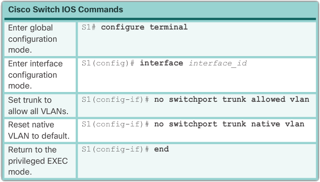
The following example shows the commands used to reset all trunking attributes of a trunking interface to the default settings. The show interfaces f0/1 switchport command reveals that the trunk has been reconfigured to a default state.
S1(config)# interface f0/1 S1(config-if)# no switchport trunk allowed vlan S1(config—if)# no switchport trunk native vlan S1(config-if)# end S1# show interfaces f0/1 switchport Name: Fa0/1 Switchport : Enabled Administrative Mode : trunk Operational Mode: trunk Administrative Trunking Encapsulation: dot1q Operational Trunking Encapsulation: dot1q Negotiation of Trunking: On Access Mode VLAN: 1 (default) Trunking Native Mode VLAN: 1 (default) Administrative Native VLAN tagging: enabled
Following example, the sample output shows the commands used to remove the trunk function from the F0/1 switch port on switch S1. The show interfaces f0/1 switchport command shows that the F0/1 interface is now in static access mode.
S1(config)# interface f0/1
S1(config—if)# switchport mode access
S1(config-if)# end

S1# show interfaces f0/1 switchport
Name: Fa0/1
Switchport: Enabled
Operational Mode: static access
Administrative Trunking Encapsulation: dot1q
Operational Trunking Encapsulation: native
Negotiation Of Trunking: Off
Access Mode VLAN: 1 (default)
Trunking Native Mode VLAN: 1 (default)
Administrative Native VLAN tagging: enabled
Verify trunk configuration
The following example shows the configuration of switch port F0/1 on switch S1. The configuration is verified with the show interfaces interface-ID switchport command.
S1(config)# interface f0/1
S1(config-if)# switchport mode trunk
S1(config—if)# switchport mode trunk native vlan
S1(config-if)# end

S1# show interfaces f0/1 switchport
Name: Fa0/1
Switchport : Enabled
Administrative Mode : trunk
Operational Mode: trunk
Administrative Trunking Encapsulation: dot1q
Operational Trunking Encapsulation: dot1q
Negotiation of Trunking: On
Access Mode VLAN: 1 (default)
Trunking Native Mode VLAN: 99 (VLAN0099)
Administrative Native VLAN tagging: enabled
Voice VLAN: none
Administrative private—vlan host-association: none
Administrative private—vlan mapping: none
Administrative private—vlan trunk native VLAN: none
Administrative private—vlan trunk native VLAN tagging: enabled
Administrative private—vlan trunk encapsulation: dot1q
Administrative private—vlan trunk normal VLANs: none
Administrative private—vlan trunk associations: none
Administrative private—vlan trunk mappings: none
Operational private—vlan: none
Trunking VLANs Enabled: ALL
Pruning VLANs Enabled: 2—1001
The top highlighted area indicates that the management mode of port F0/1 is set to trunk. The port is in trunking mode. The next highlighted area verifies that the native VLAN is VLAN 99. Later in the output, the highlighted area at the bottom indicates that all VLANs on the trunk are enabled.
Dynamic Trunking Protocol
Ethernet trunk interfaces support several trunking modes. An interface can be set to trunking or nontrunking, or to negotiate trunking with its neighbor interface. Trunk negotiation is managed by the Dynamic Trunking Protocol (DTP), which works only on a point-to-point basis between network devices.
DTP is a Cisco proprietary protocol that is automatically enabled on Catalyst 2960 and Catalyst 3560 series switches. Switches from other suppliers do not support DTP. DTP manages trunk negotiation only if the port on the neighboring switch is configured in a trunk mode that supports DTP.
The default DTP configuration for Cisco Catalyst 2960 and 3560 switches is dynamic automatic, as shown in the following image on interface F0/3 of switches S1 and S3.
 Initial DTP configuration
To enable trunking from a Cisco switch to a device that does not support DTP, use the switchport mode trunk and switchport nonegotiate interface configuration mode commands. This causes the interface to become a trunk, but not generate DTP frames.
 DTP interaction results
In the preceding figure, the connection between switches S1 and S2 becomes a trunk because the F0/1 ports on switches S1 and S2 are configured to ignore all DTP advertisements and to enter and remain in trunk port mode. The F0/3 ports on switches S1 and S3 are set to dynamic auto, so the negotiation results in access mode status. This creates an idle trunk connection. When configuring a port to be in trunk mode, using the switchport mode trunk command . There is no ambiguity about the condition of the trunk; it's always on. With this configuration it is easy to remember what state the trunk ports are in; if the port is supposed to be a trunk, the mode is set to trunk.
Negotiated interface modes
Ethernet interfaces on Catalyst 2960 and Catalyst 3560 Series switches support several trunking modes using DTP:
- switchport mode access – Puts the interface (access port) into permanent idle mode and negotiates to convert the link to a non-hull link. The interface becomes a non-trunk interface regardless of whether the adjacent interface is a trunk interface.
- switchport mode dynamic auto – Enables the interface to convert the link to a trunk link. The interface becomes a trunk interface if the adjacent interface is set to trunk or desired mode. The default switchport mode for all Ethernet interfaces is dynamic automatic.
- switchport mode dynamic desirable – Have the interface actively attempt to convert the link to a trunk link. The interface becomes a trunk interface if the adjacent interface is set to trunk, desirable, or automatic mode. This is the default switchport mode on older switches, such as the Catalyst 2950 and 3550 series switches.
- switchport mode trunk – Places the interface in permanent trunking mode and negotiates to convert the adjacent link to a trunk link. The interface becomes a trunk interface even if the adjacent interface is not a trunk interface.
- switchport nonegotiate – Prevents the interface from generating DTP frames. You can use this command only when the interface switch port mode is access or trunk. You must manually configure the adjacent interface as a trunk interface to establish a trunk connection.
The following table illustrates the results of the DTP configuration options at opposite ends of a trunk link connected to the Catalyst 2960 switch ports.
 DTP negotiated interface modes
Configure trunk links statically whenever possible. The default DTP mode depends on the Cisco IOS software version and the platform. To determine the current DTP mode, run the show dtp interface command , as shown in the following example.
S1# show dtp interface f0/1
DTP information for FastEthernet0/1:
  TOS/TAS/TNS:                              TRUNK/ON/TRUNK
  TOS/TAS/TNS:                              802.1Q/802.1Q/802.1Q
  Neighbor address 1:                       0CD99D23F81
  Neighbor address 2:                       00000000000
  Hello timer expiration (sec/state):       never/STOPPED
  Access timer expiration (sec/state):      never/STOPPED
  Negotiation timer expiration (sec/state): never/STOPPED
  FSM state:                                S6:TRUNK
  # times multi & trunk                     0
  Enabled:                                  yes
  In STP:                                   no
Troubleshoot VLANs and trunks
IP addressing problems with VLAN
Each VLAN must correspond to a unique IP subnet. If two devices in the same VLAN have different subnet addresses, they cannot communicate. This is a common problem and it is easily resolved by identifying the incorrect configuration and changing the subnet address to the correct one.
In the following image, PC1 cannot connect to the web/TFTP server shown.
 IP problem within a VLAN
A check of PC1's IP configuration settings shown in the following example reveals the most common error when configuring VLANs: an incorrectly configured IP address. PC1 is configured with the IP address 172.172.10.21, but it should have been configured with 172.17.10.21.
PC1> ipconfig
IP Address..............: 172.172.10.21
Subnet Mask.............: 255.255.255.0
Default Gateway.........: 0.0.0.0

PC1>
The PC1 Fast Ethernet configuration dialog shows the updated IP address 172.17.10.21. The following example shows the output at the bottom that PC1 has reconnected to the Web/TFTP server at IP address 172.17.10.30.
 Change IP address
PC1> ping 192.17.10.30
Pinging 172.17.10.30 with 32 bytes of data:
Reply from 172.17.10.30: bytes=32 time=147ms TTL=128
Missing VLANs
If there is still no connection between devices in a VLAN, but IP addressing issues have been ruled out, refer to the following troubleshooting flowchart:
 Missing VLANs
Step 1. Use the show vlan command to check if the port belongs to the expected VLAN. If the port is assigned to the wrong VLAN, use the switchport access vlan command to correct the VLAN membership. Use the show mac address-table command to check which addresses have been learned on a particular port on the switch and which VLAN that port is assigned to.
Step 2. If the VLAN to which the port is assigned is deleted, the port becomes inactive. Use the show vlan or show interfaces switchport command.
Use the show mac-address-table command to display the MAC address table. The following example shows MAC addresses learned on the F0/1 interface. It can be seen that MAC address 000c.296a.a21c was learned on interface F0/1 in VLAN 10. If this number is not the expected VLAN number, change the port VLAN membership using the switchport access vlan command.
S1# show mac address-table interface FastEthernet 0/1
        Mac Address Table
-------------------------------------------

Vlan  Mac Address       Type        Ports
----  -----------       --------    -----
10    000c.296a.a21c    DYNAMIC     Fa0/1
10    000f.34f9.9181    DYNAMIC     Fa0/1
Total Mac Addresses for this criterion: 2
Each port in a switch belongs to a VLAN. If the VLAN to which the port belongs is deleted, the port becomes inactive. Any ports belonging to the VLAN that was deleted will not be able to communicate with the rest of the network. Use the show interface f0/1 switchport command to check if the port is inactive. If the port is inactive, it is not functional until the missing VLAN is created using the vlan vlan_id command.
S1# show interfaces FastEthernet 0/1 switchport
Name: Fa0/1
Switchport : Enabled
Administrative Mode: static access
Operational Mode: static access
Administrative Trunking Encapsulation: dot1q
Operational Trunking Encapsulation: native
Negotiation of Trunking: Off
Access Mode VLAN: 10 (Inactive)
Trunking Native Mode VLAN: 1 (default)
Administrative Native VLAN tagging: enabled
Voice VLAN: none
Introduction to trunk troubleshooting
A common task of a network administrator is to troubleshoot the formation of trunk connections or links that behave incorrectly as trunk connections. Sometimes a switch port behaves like a trunk port even if it is not configured as a trunk port. For example, an access port can accept frames from VLANs that are different from the VLAN to which it is assigned. This is called VLAN leaks.
The following figure shows a flowchart with general guidelines for troubleshooting trunk problems.
 Troubleshoot trunk problems
To troubleshoot problems when no trunk is formed or when VLAN leaks occur:
Step 1: Use the show interfaces trunk command to verify that the local and peer-native VLANs match. If the native VLAN does not match on both sides, VLAN leak occurs.
Step 2: Use the show interfaces trunk command to check whether a trunk has been established between switches. If possible, configure trunk connections statically. Cisco Catalyst switch ports use standard DTP and attempt to establish a trunk connection.
Use the show interfaces trunk command to display the status of the trunk, the native VLAN used on that trunk link, and to verify trunk establishment. The example in Figure 2 shows that the native VLAN on one end of the trunk link has been changed to VLAN 2. If one end of the trunk is configured as native VLAN 99 and the other end is configured as native VLAN 2, a frame sent from VLAN 99 on one side is received on VLAN 2 on the other side. VLAN 99 leaks into the VLAN 2 segment.
CDP displays a native VLAN mismatch notification on a trunk link with this message:
*Mar 1 06:45:26.232: %CDP-4-NATIVE_VLAN_MISMATCH: Native VLAN mismatch discovered on FastEthernet0/1 (2), with S2 FastEthernet0/1 (99).
Connection problems occur in the network when a native VLAN mismatch exists. Data traffic for VLANs other than the two configured native VLANs propagates successfully over the trunk link, but data associated with either native VLANs does not propagate successfully over the trunk link.
As shown in the following example, native VLAN mismatch issues do not prevent trunk formation. To resolve the native VLAN mismatch, configure the native VLAN as the same VLAN on both sides of the link.
S1# show interfaces f0/1 trunk

Port       Mode     Encapsulation  Status     Native vlan
Fa0/1      auto     802.1q         Trunking   2
Common problems with trunks
Trunking problems are usually associated with incorrect configurations. When configuring VLANs and trunks on a switched infrastructure, the following types of configuration errors are most common:
- Native VLAN mismatches – Trunk ports are configured with different native VLANs. This configuration error generates console messages and can cause inter-VLAN routing issues, among other things. This poses a safety risk.
- Trunk Mode Mismatch – A trunk port is configured in a mode that is not compatible for trunking on the corresponding peer port. This configuration error causes the trunk connection to stop working.
- Allowed VLANs on Trunks – The list of allowed VLANs on a trunk has not been updated with the current VLAN trunking requirements. In this situation, unexpected traffic or no traffic is sent over the trunk.
 General problems with trunks
If a problem is discovered with a trunk and the cause is unknown, begin troubleshooting by examining the trunks for a native VLAN mismatch. If that is not the cause, check for mismatches in trunk mode and finally check for the allowed VLAN list on the trunk. The next two pages explore how to solve common problems with trunks.
Trunk mode mismatch
Trunk links are normally configured statically using the switchport mode trunk command . Cisco Catalyst Switch trunk ports use DTP to negotiate the status of the link. When a port on a trunk link is configured with a trunk mode that is not compatible with the adjacent trunk port, a trunk link cannot be formed between the two switches.
 Scenario topology
In the scenario illustrated in the previous figure, PC4 cannot connect to the internal web server. The topology indicates a valid configuration. Why is there a problem?
Check the status of the trunk ports on switch S1 with the show interfaces trunk command . The output shown in the following example shows that interface Fa0/3 on switch S1 is not currently a trunk connection. Examining the F0/3 interface reveals that the switch port is in dynamic automatic mode. An examination of the trunks on switch S3 reveals that there are no active trunk ports. Closer inspection reveals that the Fa0/3 interface is also in dynamic automatic mode. This explains why the trunk is down.
Output from Switch S1
S1# show interfaces trunk
Port   Mode Encapsulation  Status    Native vlan
Fa0/1  on   802.1q         trunking  99
Port  Vlans allowed on trunk
Fa0/1 10,99
Port  Vlans allowed and active in managment domain
Fa0/1 10,99
S1# show interface f0/3 switchport
Name: Fa0/3
Swithport: Enabled
Administrative Mode: dynamic auto

Output from Switch S3
S3# show interfaces trunk

S3# show interface f0/3 switchport
Name: Fa0/3
Switchport: Enabled
Administrative Mode: dynamic auto
To resolve the problem, reconfigure the trunk mode of the F0/3 ports on switches S1 and S3, as shown in the following example. After the configuration change, the output of the show interfaces command indicates that the port on switch S1 is now trunked. mode. The output from PC4 indicates that it has again connected to the Web/TFTP server found at IP address 172.17.10.30.
Output from Switch S1
S1# config terminal
S1(config)# interface f0/3
S1(config-if)# switchport mode trunk
S1(config-if)# end

S1# show interfaces f0/3 switchport
Name: Fa0/3
Swithport: Enabled
Administrative Mode: trunk


Output from Switch S3
S3# config terminal
S3(config)# interface f0/3
S3(config-if)# switchport mode trunk
S3(config-if)# end

S3# show interfaces f0/3 switchport
Name: Fa0/3
Swithport: Enabled
Administrative Mode: trunk


Output from Computer PC4
PC4> ping 192.17.10.30
Pinging 172.17.10.30 with 32 bytes of data:
Reply from 172.17.10.30: bytes=32 time=147ms TTL=128
...
Incorrect VLAN list
To send traffic from a VLAN over a trunk, it must be allowed on the trunk. To do this, use the switchport trunk allowed vlan vlan-id command.

In the previous figure, VLAN 20 (Student) and PC5 have been added to the network. The documentation has been updated to show that the VLANs allowed on the trunk are 10, 20 and 99. In this scenario, PC5 cannot connect to the student's email server.
Check the trunk ports on switch S1 using the show interfaces trunk command as shown in the following example. The command reveals that interface F0/3 on switch S3 is correctly configured to allow VLANs 10, 20, and 99. An examination of the F0/3 interface on switch S1 reveals that interfaces F0/1 and F0/3 only allow VLANs 10 and 99. Someone updated the documentation but forgot to reconfigure the ports on the S1 switch.
Output from Switch S3
S3# show interfaces trunk
Port   Mode Encapsulation  Status    Native vlan
Fa0/3  on   802.1q         trunking  99
Port  Vlans allowed on trunk
Fa0/3 10,20,99
Port  Vlans allowed and active in managment domain
Fa0/3 10,20,99
Port  Vlans in spanning tree forwarding state and not pruned
Fa0/3 10,20,99


Output from Switch S1
S3# show interfaces trunk
Port        Mode    Encapsulation  Status    Native vlan
Fa0/1       on        802.1q       trunking      99
Fa0/3       on        802.1q       trunking      99
Port        Vlans allowed on trunk
Fa0/1       10,99
Fa0/3       10,99
Reconfigure F0/1 and F0/3 on switch S1 using the switchport trunk allowed vlan 10,20,99 command as shown in the following example. The output shows that VLANs 10, 20 and 99 have now been added to the F0/1 and F0/3 ports on switch S1. The show interfaces trunk command is an excellent tool for revealing common trunking problems. PC5 has reconnected to the student email server found at IP address 172.17.20.10.
Output from Switch S1
S1# config terminal
S1(config)# interface f0/1
S1(config-if)# switchport trunk allowed vlan 10,20,99
S1(config)# interface f0/3
S1(config-if)# switchport trunk allowed vlan 10,20,99
S1(config-if)# end

S1# show interfaces trunk
Port        Mode    Encapsulation  Status    Native vlan
Fa0/1       on        802.1q       trunking      99
Fa0/3       on        802.1q       trunking      99
Port        Vlans allowed on trunk
Fa0/1       10,20,99
Fa0/3       10,20,99
Output from Computer PC5
PC5> ping 192.17.20.10
Pinging 172.17.20.10 with 32 bytes of data:
Reply from 172.17.20.10: bytes=32 time=147ms TTL=128
...
VLAN design and security
Switch spoofing attack
There are a number of different types of VLAN attacks in modern switched networks. The VLAN architecture simplifies network maintenance and improves performance, but it also opens the door to abuse. It is important to understand the general methodology behind these attacks and the main approaches to mitigating them.
VLAN hopping allows traffic from one VLAN to be seen by another VLAN. Switch spoofing is a type of VLAN hopping attack that works by exploiting an incorrectly configured trunk port. By default, trunk ports access all VLANs and pass traffic for multiple VLANs over the same physical link, usually between switches.
In a standard switch spoofing attack, the attacker takes advantage of the fact that the default switch port configuration is dynamically automatic. The network attacker configures a system to spoof itself as a switch. This spoofing requires the network attacker to be able to emulate 802.1Q and DTP messages. By tricking a switch into thinking that another switch is trying to form a trunk, an attacker can gain access to all VLANs allowed on the trunk port.
The best way to prevent a basic spoofing attack on a switch is to disable trunking on all ports except those that specifically require trunking. Disable DTP on the required trunking ports and manually enable trunking.
Double tagging attack
Another type of VLAN attack is a double-tagging (or double-encapsulated) VLAN hopping attack. This type of attack takes advantage of the way hardware on most switches works. Most switches perform only one level of 802.1Q de-encapsulation, which allows an attacker to embed a hidden 802.1Q tag in the frame. This tag allows the frame to be forwarded to a VLAN not specified in the original 802.1Q tag. A key feature of the double encapsulated VLAN hopping attack is that it works even when trunk ports are disabled, because a host typically sends a frame on a segment that is not a trunk link.
A double tag VLAN hopping attack follows three steps:
- The attacker sends a double-tagged 802.1Q frame to the switch. The outer header has the attacker's VLAN tag, which is the same as the native VLAN of the trunk port. The assumption is that the switch processes the frame received from the attacker as if it were on a trunk port or a port with a voice VLAN (a switch should not receive a tagged Ethernet frame on an access port). In this example, assume the original VLAN is VLAN 10. The inner tag is the victim VLAN; in this case VLAN 20.
- The frame arrives at the switch, which looks at the first 4-byte 802.1Q tag. The switch sees that the frame is intended for VLAN 10, the native VLAN. The switch forwards the packet to all VLAN 10 ports after stripping the VLAN 10 tag. On the trunk port, the VLAN 10 tag is stripped and the packet is not retagged because it is part of the native VLAN. At this point, the VLAN 20 tag is still intact and has not been inspected by the first switch.
- The second switch looks only at the inner 802.1Q tag that the attacker sent and sees that the frame is destined for VLAN 20, the target VLAN. The second switch sends the frame to the victim port or floods it, depending on whether there is an existing MAC address table for the victim host.
This type of attack is unidirectional and only works if the attacker is connected to a port that is in the same VLAN as the trunk port's native VLAN. Countering this type of attack is not as simple as stopping simple VLAN hopping attacks.
 Double tagging attack
The best approach to mitigating duplicate tag attacks is to ensure that the native VLAN of the trunk ports is different from the VLAN of all user ports. In fact, it is considered a security best practice to use a fixed VLAN that is distinct from all user VLANs in the switched network as the native VLAN for all 802.1Q trunks.
PVLAN Edge
Some applications require that no traffic be forwarded at Layer 2 between ports on the same switch, so that one neighbor does not see the traffic generated by another neighbor. In such an environment, using the Private VLAN (PVLAN) Edge feature, also known as protected ports, ensures that no unicast, broadcast, or multicast traffic is exchanged between these ports on the switch (Figure 1).
 PVLAN Edge
- The PVLAN Edge function has the following features:
- A secure port does not forward traffic (unicast, multicast, or broadcast) to another port that is also a secure port, except for control traffic. Data traffic cannot be forwarded between protected ports on Layer 2.
- The forwarding behavior between a protected port and an unprotected port is as usual.
- Secure ports must be configured manually.
To configure the PVLAN Edge feature, run the switchport protected command in interface configuration mode. To disable the secure port, use the configuration mode command no switchport protected interface. To check the configuration of the PVLAN Edge feature, use the show interfaces interface-id switchport privileged EXEC mode command.
S1(config)# interface g0/1 S1(config-if)# switchport protected S1(condig-if)# end S1# show interfaces g0/1 switchport Name: GiO/1 Switchport : Enabled Administrative Mode: dynamic auto Operational Mode: down Administrative Trunking Encapsulation: dot1q Negotiating of Trunking: On Access Mode VLAN: 1 (default) Trunking Native Mode VLAN: 1 (default) Administrative Native VLAN tagging: enabled Voice VLAN: none
VLAN design guidelines
Cisco switches have a factory configuration in which standard VLANs are preconfigured to support different media and protocol types. The default Ethernet VLAN is VLAN 1. It is a best practice to configure all ports on all switches to be associated with VLANs other than VLAN 1. This is usually done by configuring all unused ports to a black hole VLAN that is not used for everything on the network. All ports used are associated with VLANs that are different from VLAN 1 and distinct from the black hole VLAN. It is also a good practice to shut down unused switch ports to prevent unauthorized access.
A good security practice is to separate management and user data traffic. The management VLAN, which is VLAN 1 by default, must be changed to a separate, separate VLAN. To communicate remotely with a Cisco switch for management purposes, the switch must have an IP address configured on the management VLAN. Users in other VLANs would not be able to establish remote access sessions to the switch unless they were routed to the management VLAN, providing an additional layer of security. The switch must also be configured to accept only encrypted SSH sessions for remote management.
All control traffic is sent on VLAN 1. Therefore, when the native VLAN is changed to something other than VLAN 1, all control traffic is tagged to IEEE 802.1Q VLAN trunks (tagged with VLAN ID 1). A recommended security practice is to change the native VLAN to a VLAN other than VLAN 1. The native VLAN should also be different from any user VLANs. Ensure that the native VLAN for an 802.1Q trunk is the same on both ends of the trunk link.
DTP provides four switch port modes: access, trunk, dynamic automatic, and dynamic desirable. A general guideline is to disable auto-negotiation. As a best practice for port security, do not use dynamic automatic or dynamic preferred switch port modes.
Finally, voice traffic has strict QoS requirements. If user PCs and IP phones are on the same VLAN, each will try to use the available bandwidth without regard to the other device. To avoid this conflict, it is a good practice to use separate VLANs for IP telephony and data traffic.
Resume
This chapter introduced VLANS. VLANs are based on logical connections rather than physical connections. VLANs are a mechanism that allows network administrators to create logical broadcast domains that can span a single switch or multiple switches, regardless of physical proximity. This feature is useful for reducing the size of broadcast domains or for logically grouping groups or users without them having to be physically in the same place.
There are different types of VLANs:
- Standard VLAN
- Management VLAN
- Native VLAN
- User/Data VLANs
- Black Hole VLAN
- Voice VLAN
On a Cisco switch, VLAN 1 is the default Ethernet VLAN, the default native VLAN, and the default management VLAN. Best practices suggest moving the native and management VLANs to another separate VLAN and moving unused switch ports to a “black hole” VLAN for better security.
The switchport access vlan command is used to create a VLAN on a switch. After you create a VLAN, the next step is to assign ports to the VLAN. The show vlan brief command displays the VLAN assignment and membership type for all switch ports. Each VLAN must correspond to a unique IP subnet.
Use the show vlan command to check if the port belongs to the expected VLAN. If the port is assigned to the wrong VLAN, use the switchport access vlan command to correct the VLAN membership. Use the show mac address-table command to check which addresses have been learned on a particular port on the switch and which VLAN that port is assigned to.
A port on a switch is an access port or a trunk port. Access ports carry traffic from a specific VLAN assigned to the port. A trunk port is a member of all VLANs by default; therefore it carries traffic for all VLANs.
VLAN trunks facilitate communication between switches by carrying traffic associated with multiple VLANs. IEEE 802.1Q frame tagging distinguishes between Ethernet frames associated with different VLANs as they traverse common trunk links. To enable trunk links, use the switchport mode trunk command . Use the show interfaces trunk command to check whether a trunk has been established between switches.
Trunk negotiation is managed by the Dynamic Trunking Protocol (DTP), which works only on a point-to-point basis between network devices. DTP is a Cisco proprietary protocol that is automatically enabled on Catalyst 2960 and Catalyst 3560 series switches.
To factory reset a switch with 1 default VLAN, use the commands delete flash: vlan.dat and delete startup-config.
This chapter also covered the configuration, verification, and troubleshooting of VLANs and trunks using the Cisco IOS CLI and covered basic security and design considerations in the context of VLANs.